Elevator Door Motor, Door Operator Box, Door Motor Drive, Door Operator Box Suzhou FUJI Precision Elevator Co.,Ltd , https://www.profuji.com
Design and manufacture of wire cutting tooling
Figure 1 shows a hydraulic flow control valve. The valve core is made of 40Cr steel, and all other machining processes have been completed. This particular process involves using a wire-cutting machine to create triangular oil-saving holes in the valve core, with an annual production volume of 3,000 units.
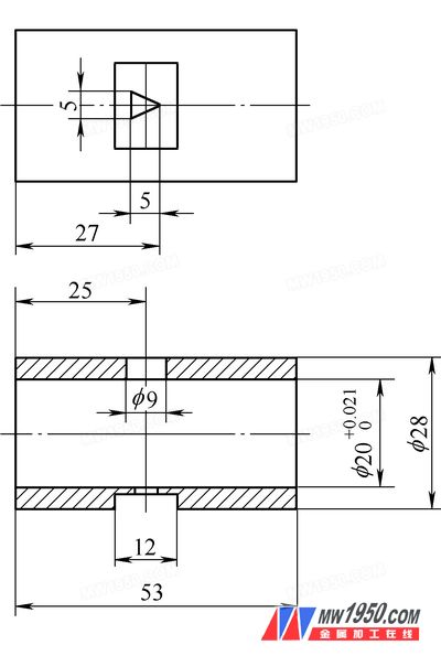
**Figure 1**
Previously, the process involved machining one piece at a time, with a pure cutting time of 1 to 2 minutes per unit. The auxiliary tasks, such as threading and unloading, took approximately the same amount of time, resulting in low overall machine tool efficiency. Traditionally, operators could manage multiple wire-cutting machines simultaneously, but operating a single machine individually led to higher labor costs. Additionally, repetitive tasks increased the risk of errors, inconsistent wire tension, and positioning inaccuracies, which sometimes resulted in defective parts.
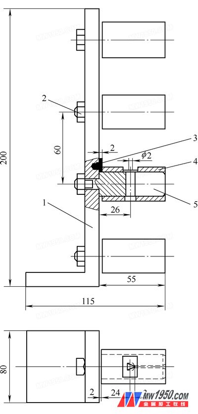
After analyzing the product design and production requirements, a new tooling system was developed, as shown in **Figure 2**, to allow for the simultaneous processing of multiple workpieces during each clamping cycle. The number of workpieces that can be processed at once depends on the height of the wire frame and the fixture setup. This approach not only ensures high-quality results but also significantly improves productivity.
### Tooling Structure
The tooling consists of a base (1) with several mandrels (5) mounted through positioning holes and secured with nuts (2). The valve body (4) is placed over the mandrel (5) in a clearance fit, and its left end surface is attracted to the equal-thickness magnet (3) fixed on the side of the base, ensuring it remains tightly attached during the cutting process.
### Operation Steps
1. Before starting the machining process, the tooling is fixed on the cross frame of the worktable using flat-nose pliers. The right plane and front side of the base are aligned, and the molybdenum wire is positioned using the "edge-touching" method or a square ruler mounted on the frame. The wire is then removed, passed through the mandrel’s process hole, and wound onto the storage tube for secure fixation. It is placed at the center of the hole to ensure proper alignment.
2. The workpiece (valve spool) is placed on the mandrel (5), and its left end is attracted to the magnet (3) by magnetic force. The molybdenum wire passes through the threading hole of the workpiece, goes around the guide wheel, and is tensioned and fixed on the storage tube. Adjustments are made visually to align the wire with the center of the threading hole before starting the automatic cutting program. The circumferential and axial positions are fine-tuned using the table movement. A vernier caliper is used to measure the distance between the wire and the positioning face, ensuring the triangle cut matches the pattern. After confirmation, the automatic cutting process begins. Following the first inspection, further adjustments are made to improve the accuracy of the triangular cut.
### Cutting Force Analysis
The weight of the valve spool (4) is supported by the mandrel (5). During cutting, the main force comes from the impact of the cutting fluid, which is largely carried by the mandrel along with the gravitational force. The axial component of the force is absorbed by the magnet. Practical tests have confirmed that the magnet’s holding force is sufficient to securely fix the spool axially. The advantage of magnetic clamping is that it allows for easy adjustment of the workpiece’s circumferential position without releasing the clamping force.
### Degree of Freedom Analysis
This tooling restricts the workpiece to five degrees of freedom: the long mandrel limits four degrees, while the base surface limits one. However, there is no circumferential positioning, so the workpiece can rotate freely. Visual observation is used to adjust the position so that the molybdenum wire is centered in the threading hole.
### Handling Precautions
The base must be manufactured precisely, with the mandrel fixing holes perpendicular to the right end surface and aligned with the front surface of the tooling. The mandrel must also meet strict tolerances: the outer diameter of 20 mm must fit loosely within the valve core hole, and the left end surface must be perpendicular to the axis of the outer cylindrical surface. These measures ensure consistent alignment of the spindle axes relative to the wire-cutting path.
If the mandrel process hole is not parallel to the base height, interference may occur, leading to damage to the molybdenum wire. In practice, an attempt was made to fully position the tooling using a 12 mm wide groove bottom surface to limit the valve core's circumferential movement. However, due to the positional accuracy of the threading hole in the previous process, the wire could not pass straight through the valve core’s hole, causing frequent breakage and waste. Therefore, the incomplete positioning scheme described in this paper was adopted.
Given the small size of the threading hole (only 2 mm), it was challenging to thread the wire on the table, especially when multiple pieces were processed together. To address this, the tooling mandrel was redesigned. A through-groove was cut on the right side of the mandrel’s process hole, allowing the workpiece to be threaded outside the tooling first. Then, the sleeve and molybdenum wire were inserted into the tooling, with the wire passing through the groove.
Regular cleaning of the tooling is essential, especially the magnets, to prevent chip accumulation that could affect positioning accuracy. Improving the precision of the parts and the assembly of the tooling can enhance overall performance. The first inspection is particularly important, as proper positioning adjustments help avoid batch waste.
### Conclusion
After years of practical use and continuous improvements, the tooling has proven to be reliable and efficient. It ensures consistent quality in the machined parts and significantly boosts both machine tool and labor efficiency. The design of the tooling can also be adapted for batch processing of similar components.