The realization of the 3D standard parts library system based on parametric template parts is based on the realization method of the 3D standard parts library of parameterized template parts. In UG, the size parameters appear in the form of expressions, as shown in Figure 2, all the features are There are objects associated with it, and each object is referenced by their unique identifier tag. When obtaining the expression of the template part, first obtain the part identification, and then obtain the identification of all the expressions by the expression in the UG to obtain all the information of the expression. Expressions such as w=40, D=w/6 are stored in a variable. To modify the expression data, first obtain the value of the entire expression, and then split the expression into the expression name and expression data. Next, assign the name and data to the variable respectively, generate a new expression based on the data selected by the user, assign the model to the model, implement the parameter modification, and finally refresh the model, and add the generated new model to the user's current environment, as shown. Implementation method should pay attention to the fact that when modifying the expression, the system does not directly modify the expression of the template part, but copies the standard part template part to the directory where the user's current file is located, and the mapping mechanism of the copied template part through the corresponding parameters. Parametric dimension drive to generate instantiated standard parts, which can avoid unnecessary modifications to the template parts and improve safety. 22 The standard parts library based on parameterized template parts is divided into standard parts library. It is divided into four parts: standard graphics library, standard parameter library, management module and application interface. 1) Standard graphics library: Divided into three-dimensional graphics library of template parts and two-dimensional preview graphics library of template parts. The 3D library is used to store template parts, while the 2D library stores 2D CAD part drawings for preview. 2) Standard parameter library: store various data of the standard parts library, including hierarchical relationship, feature code number, template part path, two-dimensional preview picture path, and various standard part sizes and structure information of template parts, for adding standard parts. When exporting. 3) Management module: Provides management of standard parts graphics library and parameter library. Provide a database interface, including adding, modifying, deleting, and sorting the parameter library data; modifying the storage path of the graphics library graphics and adding and deleting graphic data of the graphics library. Application interface: responsible for parameterized size driving. The template part is copied to the current environment, and the data is extracted from the corresponding database according to the user's selection, and the copied copy of the template part is driven by the parameterization mechanism by the corresponding parameter mapping mechanism to generate a standard instantiation standard component. The establishment of the standard parameter library is based on the flexibility, versatility of the system and the assembly relationship between the standard parts. The author divides the standard parts into three parts: standard parts, standard combinations, and typical structures. Standard parts refer to the standardized minimum functional parts that make up the fixture. They are generally composed of national standard parts and user-defined features such as screws, nuts, washers, drill sleeves, pins, etc. The standard combination is a typical combination of fixtures that are assembled from standard parts by implementing different assembly relationships, such as splints, handles, hold-down devices, positioning devices, and the like. The typical structure refers to the parameterized standard fixture structure, which is composed of standard components and standard combinations through a certain assembly relationship. According to the above division, the fixture standard parts are classified in the database, and are divided into three parts: standard parts, standard combinations and typical structures. The standard parts list is classified according to the standard parts in the Mechanical Parts and Parts Production Atlas, and is divided into three tree structures. For example, the standard parts library contains six types of joints and fastenings, and operating parts. There are eight sub-classes such as bolts, screws and nuts in the connection and fastening. The bolts also include hex head bolts - Class C, Hexagon head bolts - Full thread - Class C, T-slot bolts and other standard parts. According to the above classification and database functions, the standard part parameter library is divided into a primary index table, a secondary index table, a parts list, and a parameter value table. The standard combination table and the typical structure table are divided into two layers. The first layer is used to store the name and code of the component or structure, and the second layer is used to store the assembly relationship. These assembly relationships are provided in the UG, such as surface fitting ( Mate), face alignment (Align), angle constraint (Angle) and other assembly relationships. The specific database structure is as shown. The standard parameter library is established in the management module. Since the management module has database creation rules, this can prevent accidental errors in the process of building the database, and is more intuitive and easy to operate. Conclusion Based on the parameter-building template part construction method, the parameters are controlled with as few variables as possible, occupying less disk space of the system, realizing fast and accurate graphic design; the standard part model and parameter data are independent and related to each other, and the parameter data is easy to expand. The instantiated size data of each standard part corresponds to a table in the database, and the user can conveniently edit the data record; the standard combination table and the typical structure table are used to store the assembly relationship between the parts of the typical combination of the fixture, and the user can These relationships quickly generate a standard fixture structure; the management module is used to implement the establishment of the standard library inside the UG, effectively avoiding the improper operation errors in the database construction and protecting the data security.
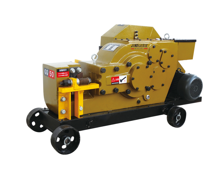
Special rebar splicing machine, which is different Common Rebar Cutting Machine. They're different from the machine structure, cutting range and so on.
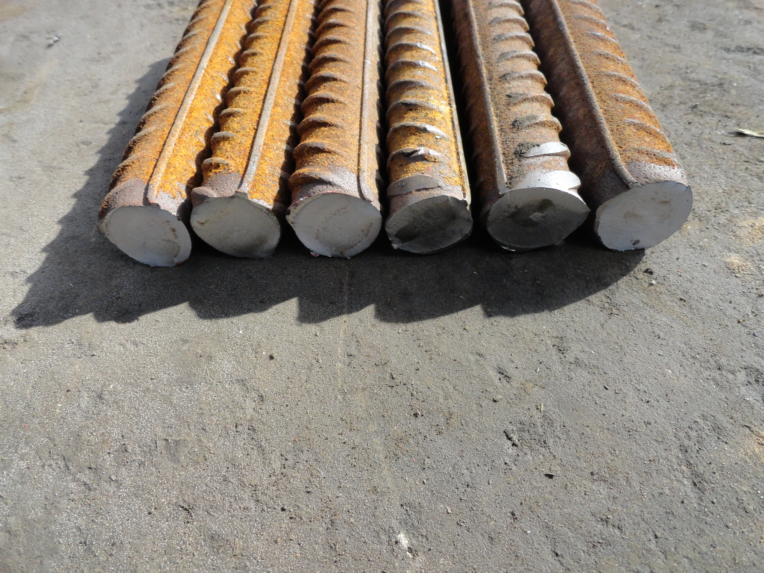
In addition to all features of common rebar curring machine, it is an ideal cutting machine for processing qualified rebar parallel thread.
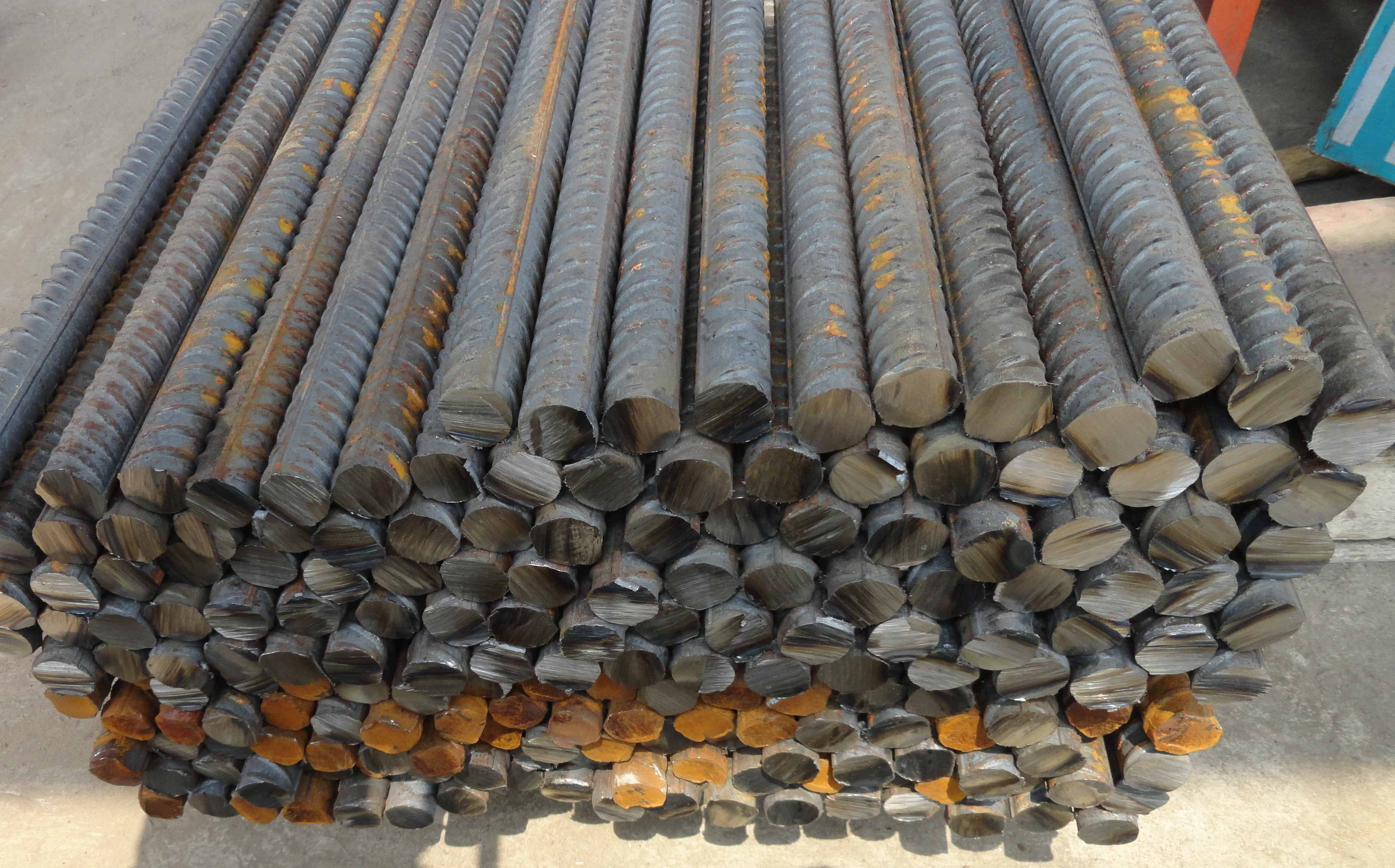
Special Rebar Cutting Machine also can be used to cut normal carbon steel rod, hot rod steel, deformed steel, flat steel, square steel, and angle steel in machine processing and construction projects.
The cutting head is round, straight, non-angular and flat without angle.
Special Rebar Cutting Machine Special Rebar Cutting Machine,Automation Steel Rebar Cutting Machine,Construction Rebar Cutting Machine,High Speed Rebar Cutting Machine BAODING JINDI MACHINERY CO., LTD , http://www.rebarconnector.com

