2, computer implementation using VC6.0 under the class provided by AutoCAD company to develop ObjectARXA program, first in VC++6.0, select ObjectARX2000 AppWizard option, and choose to support MFC, generate a project 3B, the structure of the program is: Third, the conclusion Previous page
Although there are many types of tapping screws, they all have the following similarities: Round head Tapping screw,hex tapping screw,flat head tapping screw,pan head tapping screw,truss head tapping screw Shenzhen Lanejoy Technology Co.,LTD , https://www.grill-grid.com
(1) Use acedRegCmds->addCo mma nd("3B", "3B",
"3B", ACRX_CMD_MODAL, callArx); statement registers an ARX command (2) program interface is acrx
EntryPoint(AcRx:AppMsgCodemsg,void*pkt)
{switch(msg)}
Case AcRx::kInitAppMsg:
Acrx Dynamic L inker ->unlockApplication(pkt);
Acrx Dynamic L inker ->registerAppMDIAware(pkt);
InitApplication(); Break;
Case AcRx::kUnloadAppMsg;
UnloadApplication();Break;}
Return AcRx::kRetOk;}
(3) Combining the programming principles of VC++6.0 and ARX, in the ARX program framework, write the program for reading graphic information, linear cutting program, arc cutting program and curve cutting program fitted by straight line or arc, relevant The parameter setting program, etc., is finally compiled to generate an ARX command consistent with the CAD content command, loaded and run in AutoCAD, and generates some 3B commands and molybdenum wire center trajectory by inputting some related parameters (molybdenum wire radius, offset direction, etc.). Graphics. 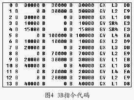

The program running results show that the automatic calculation method of the cutting die edge size and the automatic programming interface based on AutoCAD are combined in the line cutting, which realizes the automatic calculation of the cutting edge size by the AutoCAD graphic file and automatically generated from the calculated graphic information. The 3B instruction code of wire cutting processing improves the calculation efficiency and automation degree of the system. At the same time, the software interface uses MFC under VC+6.0 and ARX environment as the program carrier, and has a good man-machine interface, which can be based on the specific requirements of the process. The processing route is adjusted and modified at any time, which has good practicability.
(1) are generally made of carbonized carbon steel (accounting for 99% of total production). It can also be made of stainless steel or non-ferrous metals.
(2) The product must be heat treated. Carbon steel tapping screws must be carbonized and stainless steel tapping screws must be solution hardened. In order to make tapping screws to meet the requirements of the standard of mechanical properties and performance.
(3) The product surface hardness is high, the core toughness is good. That is, "soft inside strong outside". This is a major feature of tapping Screw performance requirements. If the surface hardness is low, it can not be screwed into the matrix; If the core toughness is poor, a twist will break, can not be used. So "inside soft outside steel" is self-tapping screw to meet the use of performance, very important requirements.
(4) The surface of the product needs surface protection treatment, generally electroplating treatment. Some product surface must be treated by phosphate (photostatting), such as wall panel self - tapping screws for photostatting.
(5) Production by cold heading process. It is recommended to use high-speed cold heading machine and high-speed wire rolling machine or high-speed planetary wire rolling machine. High speed is emphasized here to ensure product quality. Only the head of tapping screw produced by high-speed machine is well formed and the thread quality is high.