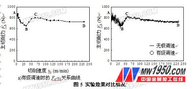
5 experimental system and effect comparison 5.1 Experimental System Figure 4 shows the experimental system for the CA6140 lathe variable frequency speed measurement cutting force. For easy observation and operation, the inverter's digital operator, buttons and sliding rheostats are mounted on the equipped control panel. The cutting force was measured using a Kistler 9257A dynamometer, a 5807A charge amplifier, and a computer data acquisition system. 5.2 Comparison of experimental results The workpiece material used in the experiment is 45 steel round bar (normalized, 180HBS). The diameter of the experiment is d=82mm, and n0 =900r/min is selected. From formula (2), vc can be stepless in the range of 0~232m/min. Variety. If the speed of the spindle is used to adjust the spindle speed, vc can get 22 points from 2.57 to 232 m/min, but according to the formula (1), it can be seen that there are only 5 points between 20 and 50 m/min. The tool of the laboratory is YT15 indexable external turning tool, γo=14o, αo=αo′=6o, κr=75o, κr′=15o, λs= -6o, rε=0.4mm. The cutting amount is ap=1mm, f = 0.1mm / r. The experiment firstly uses the speed controller to adjust the spindle speed, and the main cutting force at 22 cutting speeds of 2.57~232m/min is measured. The data processing results in the Fc-vc relationship curve with stepwise speed regulation. Then, the inverter is steplessly regulated, so that the vc continuously rises from 2.57m/min to 232m/min, and the Fc-vc relationship curve can be obtained directly in the stepless speed regulation. Figure 5 shows the comparison of experimental results. It can be seen from Fig. 5 a) that the minimum point B in the hump curve appears near vc=30min/min, which is obvious, but the maximum point C is not obvious and should be between vc=50-75min/min. It is not difficult to see from Fig. 5 b) that the minimum value point B is also near vc=30min/min, and the maximum value point C appears between the two points in the stepwise speed regulation, thus indicating the stepless speed regulation. The hump curve of cutting force and cutting speed can be obtained clearly and completely. In addition, it can be seen from Fig. 5 b) that the motor and the gear are slightly vibrated at low speed, and the built-up edge periodically generates and falls off. The comprehensive cause causes the AB section cutting force signal to fluctuate greatly; BC In the segment, the running speed of the motor and the gear is increased, the vibration is reduced, and the built-up edge is gradually disappeared, so that the fluctuation of the cutting force signal is reduced. 6 Conclusion (1) In order to obtain the hump curve of the cutting force when the cutting speed is continuously changed, the Delta inverter is used to steplessly adjust the main motor of the machine tool, and an additional control circuit is designed to facilitate the entry and exit of the inverter. After using the inverter, The spindle speed is determined by the motor operating frequency and the speed control handle; (2) Stepless speed regulation can prevent the cutting speed from being affected by the change of the diameter of the workpiece. Through experimental comparison, the hump curve of cutting force and cutting speed can be obtained clearly and completely during stepless speed regulation; (3) The inverter is used to steplessly adjust the main motor of the machine tool, and the cutting speed can be kept constant in the tool wear test, which expands the application range. About the Author Zhang Yue (1980-), male, School of Mechanical Engineering, Shenyang University of Technology, research direction of new machining technology. references [1] Editor-in-Chief Chen Rizhen. Metal cutting principle (2nd edition). Beijing: Mechanical Industry Press, 2002. [2] Han Rongdi editor. Metal cutting principle and tool (3rd edition). Harbin: Harbin Institute of Technology Press, 2007. [3] MC Shaw, Metal Cutting Principles. Oxford: Claredon Press, 1984. [4] EM Trent, Metal cutting (3rd Edition.). Oxford: Butterworth Heinemann, 1991. [5] Zhongda Dentsu Co., Ltd. VDF-V High Performance Magnetic Beam Vector Control AC Motor Driver User Manual, 2003.
Sealand is a trustworthy manufacturer of CNG Dispenser Mass Flow Meter, LNG Dispenser Mass Flow Meter, LPG Dispenser Mass Flow Meter, ATEX, CE & IECEx approved.
With its high accuracy, wide rangeability and reliable performance, Sealand meter has been applied in many kinds of industries during the last 8 years. Unlike others who only focus on the measurement of liquid at normal pressure & temperature, Sealand has conquered the difficulty in the measurement under severe conditions, such as high pressure, high viscosity, high & low temperature.
Here are the pictures of Sealand Mass Flow Meter in Dispenser for your reference.
CNG Dispenser Mass Flow Meter, LNG Dispenser Mass Flow Meter, LPG Dispenser Mass Flow Meter Zhejiang Sealand Technology Co., Ltd. , https://www.sealandflowmeters.com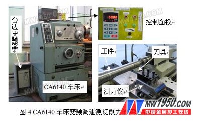
Previous page 1 2 3 Next page
Take CNG (compressed natural gas) for example. As the saying goes, the meter can measure anything else if it can measure CNG. It is quite hard to measure gas under high pressure. The sensor must be able to bear high pressure; in this way, the thickness of flow tube must be increased, so the transmitter shall be more sensitive to detect the signal; however, Sealand made it. Sealand's first model is specially designed for CNG dispenser, and now thousands of this model are put into use on the market.


